Insights from CPTu and Seismic Cone Penetration Testing in the Kathmandu Valley, Nepal
 Charlotte E. L. Gilder
 Rama Mohan Pokhrel
 Flavia De Luca
 Paul J. Vardanega
- Department of Civil Engineering, University of Bristol, Bristol, United Kingdom
Seismic hazard assessment often relies on static piezocone penetration tests (CPTu) to estimate the cyclic resistance ratio (CRR) and for the evaluation of in situ soil behavior. This article presents CPTu data acquired in the Kathmandu valley sediments and makes use of established CPTu interpretation procedures to assess the soil in situ properties. Up to this point predominantly SPT data and limited shear wave velocity measurements have been relied upon to assess the variability and seismic response of soil deposits underlying Kathmandu. This article provides 1) additional data to add to the existing SAFER/GEO-591 database, 2) new shear-wave velocity measurements, and 3) initial estimates of CRR at the sites visited. Based on the work presented in this article, it is concluded that a more detailed methodology is needed for liquefaction assessment mainly due to the presence of saturated silts in the valley.
Introduction
Nepal has many rural populations as well as urbanized areas with building stock whose frequency and distribution of structural typologies remain uncertain. The impact of earthquake hazard is likely to increase as urbanization of the world’s cities increases (United Nations, 2018). Areas where urbanization is dominated by building stock constituting mainly non-engineered local construction are subject to even higher vulnerability due to earthquakes (e.g., Giordano et al., 2021). Nepal is an example of such an area. A lack of high-quality information to aid the development of retrofitting or reconstruction efforts is a barrier to the improvement of seismic resilience. Similarly, the earthquake hazard assessment relies on the availability of high-quality ground data. Measurements of shear wave velocity (Vs) using established methods of good quality (cf. Wair et al., 2012) are sparse in the Kathmandu valley (Gilder et al., 2020). The Gorkha earthquake death toll was approximately 9,000 (USGS, 2016). The availability of high-quality geotechnical testing data and geophysical equipment for the measurement of Vs is driving uncertainty in the assessment of site response.
Various field missions soon after the Gorkha earthquake reported incidences of liquefaction and confirmed that there was considerable uncertainty in ground conditions (e.g., Aydan and Ulusay, 2015; Goda et al., 2015; Hashash et al., 2015; Wilkinson et al., 2019). Gilder et al. (2020) presented a database of borehole records, standard penetration tests (SPTs), laboratory tests, and shear-wave velocity data which were used to explain in situ soil characteristics of the region. In the typically low-strength and thinly laminated soils (as shown in the borehole records in Gilder et al. (2019b)) the use of SPT-N values for assessment of soil strength is not optimal.
After the 2015 Gorkha earthquake, recorded cases of liquefaction occurrence were relatively few, with some descriptions of sand boils and ground settlement (e.g., Moss et al., 2015; J-RAPID, 2016; Moss et al., 2017). Tilting of buildings was observed (Ohsumi et al., 2016) and seasonal changes in the water table arguably caused the liquefaction hazard to be minimized at the time of year that Gorkha occurred (Moss et al., 2017). In many areas of the valley, the earthquake led to considerable structural damage.
The cyclic resistance ratio (CRR) is used to assess between liquefiable and non-liquefiable soil conditions and traditionally involves the measurement of either the SPT-N or cone penetration test (CPT) cone resistance. These parameters are compared against the cyclic stress ratio (CSR) and are used to inform engineers of the likely liquefaction response according to measured site conditions (Robertson and Wride, 1998; Youd and Idriss, 2001; Boulanger and Idriss, 2014). The understanding of the significance and extent of possible damage that an earthquake might cause at a specific location is also largely affected by the underlying soil stratigraphy and in situ state of the soil deposits. Evaluation of the dynamic response of soil also requires the understanding of small-strain shear modulus (Gmax). Gmax can be measured in situ along with other CPT-derived parameters by performing a seismic cone penetration test (SCPT) which measures Vs.
This article presents the key findings of a ground investigation undertaken in the Kathmandu valley sediments, which produced detailed CPT profiles for the region. The primary aim of the article is to report the new shear-wave velocity measurements obtained using the SCPT equipment. At each site, a link is made between the new data and any previous geotechnical observations (taken mainly from SAFER/GEO-591, Gilder et al., 2019a; Gilder et al., 2020) to gain further insights into the site-specific geotechnical conditions. Use of geotechnical equipment, such as the CPT, is not a technique that is believed (to the best of the authors’ knowledge) to have been used previously in this part of Nepal. Geophysical equipment is available in Nepal, such as downhole seismic (see Gilder et al., 2019b), but such data are often not widely available in an open-access format. In this study, the CPT and seismic data were analyzed following current CPT interpretation frameworks. Given that this region of Nepal has few high-quality laboratory tests to inform the CPT data, these results will need to be enhanced with further testing. Furthermore, issues relating to assessment of the probability of liquefaction (Robertson and Wride, 1998; Zhang et al., 2002; Shuttle and Cunning, 2008) are discussed after examination of the results of the preliminary assessment. The problem when using existing liquefaction assessment methods is that the evidence has largely been developed from quantitative evaluation of material properties of quartzitic “clean” sands (Jefferies and Been, 2006). Further investigation will be needed to provide new insights and improvements for producing reliable, region-scale shear-wave velocity maps (e.g., De Risi et al., 2020) which influence earthquake hazard assessments (Stevens et al., 2018) and site amplification studies (e.g., Asimaki et al., 2017).
Previous Information and Site Locations
Local Geology and Geotechnical Information
This section outlines relevant geological and previous geotechnical information for interpreting the new CPT results sourced from SAFER/GEO-591 (Gilder et al., 2019a; Gilder et al., 2020) and the available literature. An overview of the local geology has been outlined in various publications (e.g., Sakai, 2001; Fujii and Sakai, 2002; Piya, 2004; Sakai et al., 2016). In summary, the Kathmandu valley can be generally considered to contain both highly plastic and low-plasticity silts and clays (Gilder et al., 2020), at states ranging from unconsolidated to slightly over-consolidated, interlayered with sands and gravel (Gilder et al., 2019b). These soils are of Pliocene to Pleistocene as well as Holocene geological age and mainly represent fluvio-deltaic and lacustrine geological depositional environments (Shrestha et al., 1998; Sakai et al., 2016).
The ground investigation was undertaken in April 2019, and a total seven different locations in the valley were visited. The sites are named by location and include: Harisiddhi—brick works (site 01), Kirtipur—open field (site 02), Kausaltar—Araniko highway (site 03), Dhobighat—riverside (site 04), Satdobato—agricultural field (site 05), Chyasal—bus depot (site 06), and Baghdol—Mal Pokhari playing fields (site 07). Figure 1 shows the location of each of these sites and Table 1 provides details of geotechnical tests from the existing database SAFER/GEO-591 (Gilder et al., 2019a; Gilder et al., 2020) as well as information of the underling geological sequences. In this case, the prefix CPT denotes locations where a CPTu (a CPT undertaken using a piezocone) was carried out and SCPT where a seismic dilatometer (Marchetti) test was undertaken.
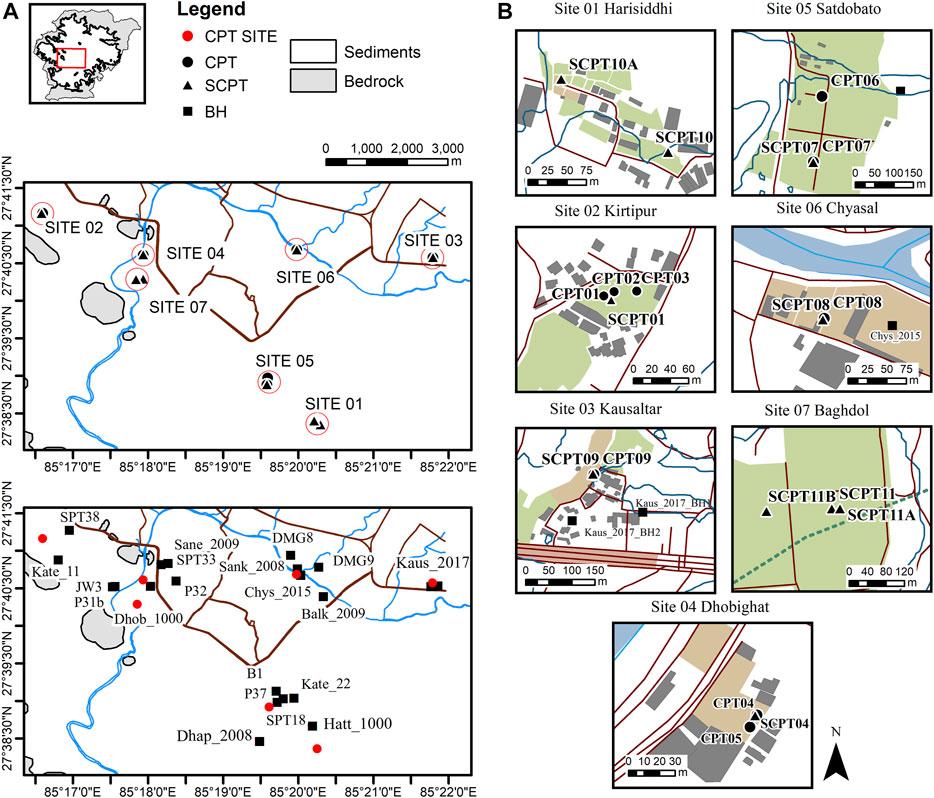
FIGURE 1. (A) Site location plan showing CPT investigation sites and historical borehole records from SAFER/GEO-591 (Gilder et al., 2019a; Gilder et al., 2020) (B) the seven CPT investigation sites.
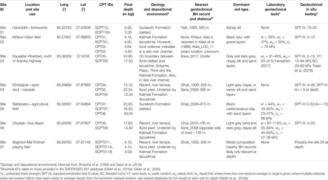
TABLE 1. Locations of CPT ground investigations, geology and closest borehole information.
When determining suitable locations for the site investigations, relevant factors considered included the spatial distribution of previous data in the earthquake prone region and the knowledge of particularly vulnerable areas from examination of main-shock and post-earthquake sequences (e.g., Goda et al., 2015). However, locations had to be positioned on disused land parcels or land for which access could be agreed quickly and which had suitable access for the testing equipment. In the sections below, each study location is discussed to highlight previous geotechnical field observations from SAFER/GEO-591. Further site photographs are available in the online repository (Gilder et al., 2021).
Site Descriptions
Site 01 – Harisiddhi
Site 01 comprises two areas of residential land, just east of a brickworks located off Satdobato–Godavari Road, in Harisiddhi, Lalitpur district. This area is at an elevation of approximately 1,315 m AMSL (above mean sea level), which reduces steeply to the west of location SCPT10A, where clay working has reduced the original ground level. These clay workings allowed inspection of the underlying sequences of SCPT10A. Site photographs are provided in Figure 2. Figure 2C indicates the amount of material that has been removed from this area due to the clay workings. The river Kodku Khola extends north to south, approximately 150 m west of location SCPT10A, which is a tributary of the Bagmati River which extends east–west centrally through the valley. The nearest borehole information to site 01 is 565 m north detailed in database record IND_Hatt_1000 (SAFER/GEO-591; Gilder et al., 2019a; Gilder et al., 2020). The descriptions at the borehole site match well with the inspected materials, the majority comprising a brownish–light-grey, sandy, silt. The borehole records also correspond to a similar level to site 01 at approximately 1,308 m AMSL. Within both IND_Hatt_1000_BH1, BH4, BH6 a medium dense gravel was observed, between depths of a minimum of 1.50 m bgl up to a maximum depth of 6.10 m bgl. Potentially a similar unit could have caused the early refusal of the SCPT at this location. The boreholes were pursued to a maximum depth of 20.0 m, indicating only minor changes of silt and sand content in logging, and SPT-N values that remain consistently in the range of 10–25 (medium dense) or firm to stiff and stiff silts below 5.0 m bgl. Sakai et al. (2016) indicates that this deposit is of deltaic origin, comprising the Sunakothi Formation.
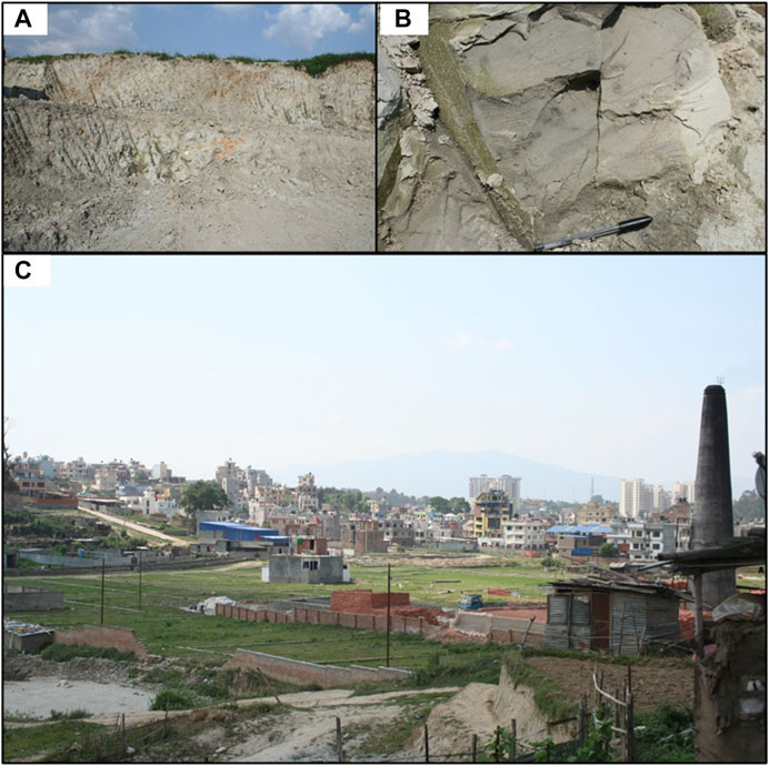
FIGURE 2. (A) Cut faces at site 01, brickworks (B) material in cut faces at site 01, surfaces are baked but show light-grey silty material (C) Harisiddhi site area, looking northwest from SCPT10A [Photos: C. E. L. Gilder].
Site 02 – Kirtipur
Site 02 is an area of grassed open land, situated in Kirtipur Municipality, located outside of the Ring Road to the west of Kathmandu. The site is generally flat at a level between 1,300–1,310 m AMSL. The greater area of Kirtipur is raised from the central city of Kathmandu and features ridges, where areas of bedrock are exposed, one of which is present 450 m southwest of the site, extending northwest to southeast at approximately 1,400 m AMSL. The nearest water course is present 230 m west, Balkhu Khola, flowing toward the Bagmati River located 2.3 km east. The authors local knowledge in this area indicates that the underlying ground comprises black clay with gravel layers for at least 10 m depth, evidenced from two local wells built in the area. The site lies within 550 m northwest of Tribhuvan University. Nearby SPT testing indicated an SPT-N range of 2–15 within the first 5.50 m bgl (record R_Unkn_1000_SPT38). Additionally, material testing reported to be from Kirtipur in Katel et al. (1996) (RES_Kate_1996_LOC11) indicated an undrained shear strength value of 79 kPa for soils at 2.50 m bgl, with a natural moisture content (w) of 29%, and liquid (wL) and plastic (wP) limits of 27 and 20%, respectively. Unfortunately, the available geotechnical records within the vicinity of site 02 do not have any logged material descriptions.
Site 03 – Kausaltar
Site 03 at Kausaltar is located within a relic river channel, just north of the Araniko Highway which forms the main link from Kathmandu to Bhaktapur. This is approximately 1.1 km east of Tribhuvan International Airport. This site was selected as it was at this location that the highway was exposed to significant movement which caused damage during the 2015 earthquake (Tiwari et al., 2018). Borehole six from the Tiwari et al. (2018) investigation is included in the database as IND_Kaus_2017_BH2 and is closest to CPT09 and SCPT09, at approximately 100 m south-west. Further west, but in the relic river channel (Figure 3A) (like the CPT tests), borehole two of Tiwari et al. (2018) includes both in situ vane shear tests and Swedish cone testing. Both tests produced similar results; at 3.40 m a range of undrained strength (cu) of 15–94 kPa and between 2 and 60 kPa for the latter testing. The borehole records in the vicinity report grey and dark-grey, clayey, silt with closely spaced, grey, sand layers, as well as thicker sequences of wet, fine-, or medium-grained sand. At IND_Kaus_2017_BH2, dark-grey, silty, clay layers are also present. In this borehole, SPT-N values range from 2 to 15. Four samples from depths ranging between 1.0 and 4.0 m from borehole 2 (Tiwari et al., 2018) were used to determine index properties and simple static, and cyclic shear tests were carried out on remolded samples. These test results are reported in Yamashiro (2017) and are summarized as follows:
• Liquid limits (wL): 31–46%
• Clay fraction (CF): 12–27%, Unified Soil Classification: CL and ML
• Vs (from laboratory bender element tests): 161–313 m/s.
• Gmax calculated from backbone curves: 26.3–30.3 MPa.
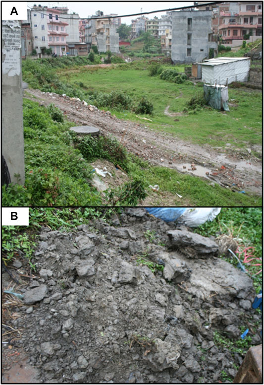
FIGURE 3. (A) Site 03, Kausaltar looking southwest from adjacent to SCPT09 into the relic river channel. (B) Materials from hand pit adjacent to CPT09 [Photos: C. E. L. Gilder].
The geological map indicates that the site is underlain by fluvio-deltaic facies but lies near to the transition to the Kalimati Formation (older lacustrine). The upper portion of CPT09 comprises recent deposits (shown in Figure 3B).
Site 04 – Dhobighat
Site 04 is located within Dhobighat, positioned between the Bagmati River, 90 m east and the Ring Road 280 m west. The area is predominantly residential, and the site formed a disused area between buildings at an elevation of 1,274 m AMSL. Nearby boreholes at 1,286 m AMSL, IND_Dhob_1000, indicated a light-grey, clayey or sandy, silt with layers of light-grey, coarse, sand occasionally with gravel. Most SPT-N values in these silts are within the range 4–14, with two higher values of 22 and 28 also reported. At two locations, the borehole logs indicate light-brown, fine, silty sand with reported SPT-N values ranging between 12 and 21. These boreholes extend to a maximum depth of 15 m. Deeper boreholes (IND_Sane_2009) located 650 m northeast indicate similar sequences of light-grey, clayey, and sandy silts and extend to 25 m but with much lower SPT-N values (not above 9). This may be indicating a change from site 04 and location IND_Dhob_1000 which are likely to be underlain by recent deposits, whereas site IND_Sane_2009 with the lower SPT values and without sand layers indicates the site is likely to be underlain at depth by the Kalimati Formation.
Site 05 – Satdobato
Site 05 is situated on land used by the Department of Agriculture in Satdobato, Lalitpur. The greater site area is approximately 6 ha used for crop growth, positioned 1 km south of the Ring Road, at an elevation of 1,320 m AMSL. The site is bounded to the east by Dhapakhel Road, which extends from the Ring Road in a north–south direction. The geological depositional environment is thought to be deltaic and evidence of a grey silty/clay surface material is found in channels due to land irrigation (also this was found stuck to the removed CPT rods). The nearest boreholes JICA (1990) wells P37 and B1 at locations 230 m east and northeast, respectively, indicate dark black carbonaceous clay with alternating layers of sand. A record from Katel et al. (1996), RES_Kate_1996_LOC22, is in Hatiban (just east of site 05) and indicates the natural water content of the soil is 44% with wL of 45% and wP of 26% at 2.50 m depth. The same sample was used for consolidated undrained triaxial testing which indicated a cu of 68 kPa. Further from the site at 800 m south, database boreholes IND_Dhap_2008 (elevation 1,328 m AMSL) describe light-grey, wet, silty clays and clayey silts. SPT-N values were taken every 1 m across nine boreholes to 35 m bgl. The SPT-N values range between 0 and 53 (mean of 13). Effective stress testing indicated cohesion values (c′) of 2–29 kPa and effective friction angle (ϕ′) between 6 and 27°. The wL ranges between 43–82% and wP ranges between 23–57%, from varying depths. Particle size distribution testing indicated fines content of >85% across 35 tests.
Site_06 – Chyasal
Site 06 is positioned in a bus depot beside the Himalaya College of Engineering, in Chyasal, northeast Lalitpur. This site is bounded to the east by the Chyasal football ground. Previous boreholes were drilled on the football ground and indicate the site is underlain by medium dense, light-grey, fine to medium sand and soft and firm, dark-grey, clayey silt. The boreholes (IND_Chys_2015) reached a maximum depth of 12 m. Particle density testing was taken at increments of depth, with results between 2.393 Mg/m³ and 2.683 Mg/m³. SPT-N values range between 4 and 23 (a mean of 10). wL ranges between 65–84%, and wP ranges between 44–63%. The water contents range between 67–113%. Ring shear testing indicates c′ and ϕ′ values of 0 and 29–32°. Undrained shear strength tests are 36 kPa at 4 m depth and 27 kPa at 9 m depth. Groundwater was encountered between 1.50 and 2.50 m depth. The site is bounded to the north by the intersection between the Bagmati River and the Manohara River, which flow northwest wards from the position of the site. Beyond the river to the north is a further geotechnical site IND_Sank_2008, which is underlain by soft, dark-grey, clayey silt, occasionally including sand or gravel. SPT-N values are slightly lower than the previous site (1–11 in silts), and groundwater was encountered between 2.30 and 2.60 m depth. Two JICA (1990) well logs are available at 500 m northwest (DMG 8) and 500 m northeast (DMG 9), indicating these sequences of clays/silts extend to between 160–180 m depth.
Site 07 – Baghdol
Site 07 is in a similar location to site 05 (just 600 m south). The site is located on the Mal Pokhari playing fields in western Lalitpur. The area is an approximately 22 ha, level (between 1,275 and 1280 AMSL) area of grassed ground situated on a bend of the Bagmati River. The river is at closest 250 m south of the investigation locations but flows around the western bounds of the site from north to south. The IND_Dhob_1000 borehole records described in site 05, Dhobighat are 450 m northeast of the site and indicate layers of grey sand and clayey or sandy silt. A ridge, the same as that described at Kirtipur, is present at the opposite side of the Bagmati River, 570 m southwest and marks a rise in elevation to 1,410 m AMSL. The river progresses around this ridge to the south. The underlying ground is assumed to be similar to that described for site 05 but with the upper portions comprising recent river deposits.
Methodology
CPTu Equipment
Geotechnical investigation methods such as the CPTu are commonly adopted where particularly soft/loose or complicated ground conditions, or build, might require a more detailed assessment. The method is also particularly useful when profiling potentially organic clays or deposits that are laminated to provide engineering parameters that are likely not available from laboratory testing due to difficulties with recovery of suitable samples. Previous investigations in the valley (Gilder et al., 2019b) indicated that both previous conditions are true for the Kathmandu valley soils. Drilling operations can often miss some vital evidence of thin laminations.
The above-mentioned points were important incentives for pursuing this study. The CPT equipment chosen was capable of fitting into two (1 m × 1 m × 1 m) boxes which could be shipped by air to Nepal. This equipment was contributed to the Seismic Safety and Resilience of Schools in Nepal (SAFER), project led from Bristol University by IN SITU site investigation, a United Kingdom based CPT company. The rig is attached to any available plant which might be present in the recipient country. In this case, a JCB 3CX excavator was chosen to aid mobility between sites, and the hydraulic jacks of the CPT rig were mounted to the front shovel (Figure 4). This setup can take all usual measurements of a traditional CPT rig but is limited only by the weight, i.e. the reaction force provided by the selected plant. The CPTu cone had a cross-sectional area (Ac) of 10 cm2, and the filter position was behind the cone at the u2 location. The CPTu soundings were conducted to a maximum depth of 24.80 m with seismic testing reaching a maximum depth of 17.50 m. Two dissipation tests were undertaken, the first at the depth of 14.51 m at site 05, location CPT07 and the second at 16.41 m, site 06, CPT08.
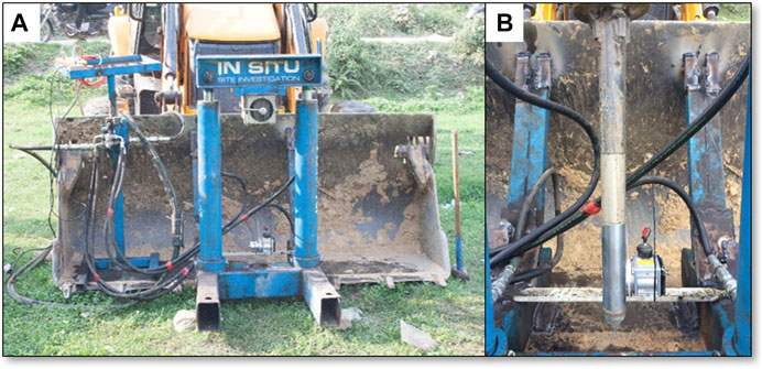
FIGURE 4. (A) Method of CPT investigation using portable CPT rig which can be welded to hired plant when reaching the country of testing (B) 10 cm2 cone penetrometer [Photos: C. E. L. Gilder].
The SCPT’s were undertaken using a seismic dilatometer probe, without the blade, containing two dual receiver geophones for receiving P and S-wave velocities, separated at approximately 0.6 m and 0.5 m apart respectively. This enabled simultaneous measurement of waves so that the true interval method for obtaining seismic velocities can be used (e.g., Stolte and Cox, 2020). In this case, the seismic dilatometer was separate from the CPTu cone; therefore, seismic readings were taken at a position adjacent to a corresponding CPTu location. This geophysical method uses the hydraulic jacks of the CPT rig to push the seismic equipment to different depths within the soil profile to determine wave velocities at increments. During testing at each increment, the seismic waves are generated by hitting a steel beam on the ground surface, a straight-line seismic wave travel path from source to receiver is assumed, and the seismic recordings are repeated three times to obtain an average. Where the coefficient of variation (COV) was found to be too high, the test was repeated until considered acceptable. Description of the equipment and the original seismic waveforms can be accessed from the data.bris repository along with raw CPTu results (Gilder et al., 2021).
CPTu Data Processing
The CPT measures the resistance of the soil measured in parameters of cone resistance (qc), sleeve friction (fs), and pore pressure (u2). Other parameters can be derived from these measurements, including pore pressure ratio (Bq) and normalized friction ratio (Fr). These normalized parameters can be calculated according to that described by Lunne et al. (1997) including updates from Robertson (2009) and Robertson (2016). During this process, the CPT measurements can also be used to provide indication of soil type, by deriving the soil behavior type index Ic (Been and Jefferies, 1993):
where Q is the dimensionless CPT resistance based on vertical stress [= (qt − σv0)/σ′v0], where qt is the corrected total cone tip resistance, σv0 is the in situ vertical total stress, and σ′v0 is the in situ vertical effective stress. The combined parameter Q (1 − Bq) + 1 can be considered in a simpler manner to be equal to (qt − u2)/σ′v0 (Jefferies and Been, 2006). Fr is equal to the sleeve friction divided by the cone resistance normalized by the total stress as a percentage [=fs/(qt − σv0) 100 (%)], and the Bq is the pore pressure ratio [=(u2 − u0)/(qt − σvo)]. The literature for determining soil parameters interpreted from the CPTu is extensive (e.g., Robertson and Campanella, 1983a; Robertson and Campanella, 1983b; Jefferies and Davies, 1991; Robertson and Wride, 1998; Jefferies and Been, 2006; Robertson, 2009) and is not reviewed in detail here, but it is mentioned that these procedures were originally calibrated using databases comprising primarily of sands (Jefferies and Davies, 1991; Jefferies and Been, 2006). It is important to adopt procedures which can represent the soils of a region. For example, development of the approach for estimation of yield stress using the CPT can be affected by lack of data of high plasticity or organic clays (Mayne and Kulhawy, 1995). Adjustments to the original sand-like procedures have been presented in updated classification charts (Robertson, 2016), reflecting the differences in interpretation of the CPT for undrained as opposed to drained conditions. Additionally, further studies focusing on analysis of CPT testing in unfamiliar geologies (Schneider et al., 2008) and better understanding of the mechanical properties which dominate the behavior for evaluation of undrained response (Shuttle and Cunning, 2007; Been et al., 2010) have been reported. These problems can occur most when in the mixed soils region, and soft saturated silts which have a low plasticity can behave like clays when classified using soil behavior type if they have low-undrained shear strength (Robertson, 2010). Typical correlations for Vs and cone penetration data, including clays and silts (Madiai and Simoni, 2004; Schneider et al., 2004; Hegazy and Mayne, 2006; Andrus et al., 2007) or aged materials including over-consolidated clays (Powell and Butcher, 2004), may be used to better define fine-grained soil relationships. However, data interpretation remains a problem for regions with less available historical geotechnical investigation data such as the Kathmandu valley.
Methodology: Assessment for Liquefaction
Although the primary aim of this work has been to determine with greater certainty the engineering properties of the soils below Kathmandu and provide new shear-wave measurements, additional information can be obtained from the CPT results. As the CPT measures the resistance of the soil, in liquefaction assessment, this is compared to the CSR or τcyc/σ′vo (defined as the ratio of the average equivalent uniform cyclic shear stress, τcyc that causes liquefaction due to the design earthquake, and σ′vo). This CSR value corresponds to that measured in laboratory simple shear tests. Early work to modify the SPT-based liquefaction assessment to the CPT equivalent was reported by publications such as Robertson and Campanella (1985) and Olsen (1997) with the major contributions summarized in Robertson and Wride (1998). As discussed in Jefferies and Been (2006) when using these methods, it is assumed that
(1) For a particular site, a characteristic qc can be determined;
(2) The soils on the site are sufficiently similar to those used to derive the original trends, that is young (Holocene), “clean sands”; and
(3) The extrapolations used to provide correction factors have a physical basis.
As the Kathmandu soils are highly variable, and for the area of the CPT investigations are mainly fine-grained, and because of the reasons described above, the Kayen et al. (2013) methodology for assessing the probability of liquefaction was used as a basis for preliminary assignment of the CRR to the soils tested. This method uses the Vs measurements directly.
CPTu Results
An example CPT result is presented in Figure 5, and the results from the remaining sites are shown in Supplementary Figures SA1–SA8 providing the measured CPT data and interpretations. Site 01 and site 07 have only velocity profiles, and these are shown in Figure 6. In the following discussion of the results, where the geological map of the region and geotechnical testing indicate similar conditions, these sites are considered together.
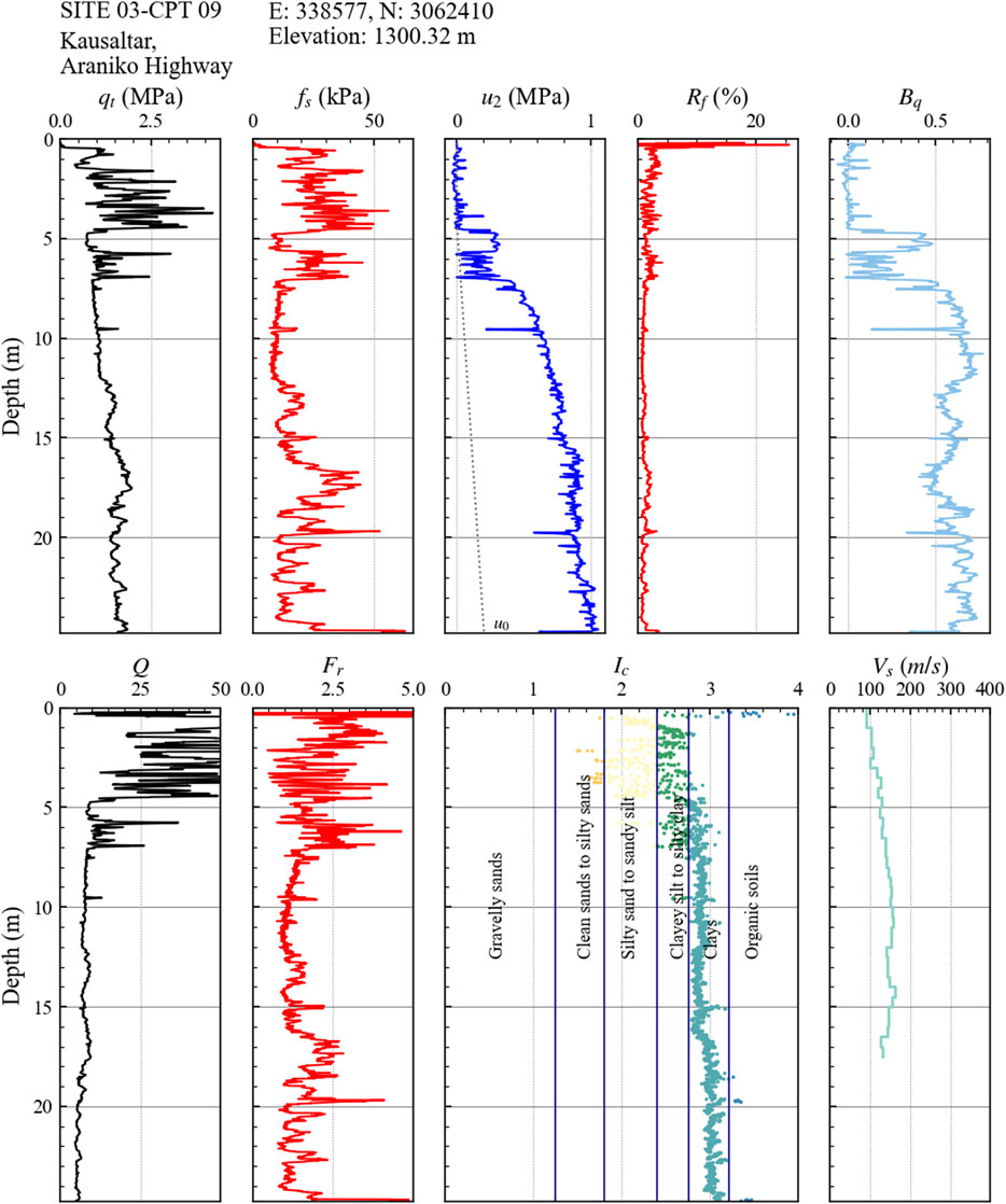
FIGURE 5. CPT results at site 03, Kausaltar.
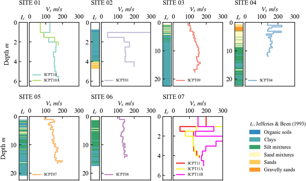
FIGURE 6. Shear-wave velocity results at the seven sites. Where a CPT result is available, the soil profile is represented as the Ic designation (Been and Jefferies, 1993).
The first result to note is that at the locations tested there is a dominance of fine-grained soils, (ISBTn > 2.6 or Ic > 2.4) and the corrected cone resistance values (qt) of these soil behavior types are low, less than 5 MPa, and typically between 1–2 MPa. The soils in this range are designated “silt-like” and “clay-like”. Recorded pore pressures (u2) reached a maximum of 1,050–1700 kPa in these silts, and the derived pore pressure ratio Bq is between at 0.65–0.78. The normalized friction ratio Fr values are typically at 1–2%. Reductions in porewater pressure can be seen where these silts are interlayered with coarser materials or organics. Figure 7 shows the results of two dissipation tests in these soils. At site 05, the dissipation rate results in an estimated T50 of 13.6 min at 14.5 m depth, indicative of a material between a silt and clay, whereas the dissipation rate at site 06, at 16.4 m is faster (8.5 min) and may indicate a greater dominance of silt.
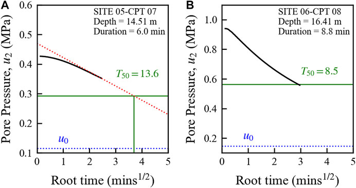
FIGURE 7. Dissipation testing against the square root of time at (A) site 05, Satdobato agricultural field and (B) site 06, Chyasal bus depot.
For the investigations closest to previous borehole data (see Table 1; Figure 1A), it is reasonable to compare the field data with the laboratory results from the previous sources. Figure 8 shows a comparison of a borehole at site 06, selected from the Chys_2015 investigation (Gilder et al., 2020), with the CPT soil behavior type results. Comparison of the soil behavior type Ic and ISBTn (Robertson and Wride, 1998; updated in Robertson, 2009) shows the material between 2.0 and 6.0 m is classified as more “sand-like” by this latter method (Figure 8C). However, the borehole unfortunately falls short of the change (at 12 m), shown in the Ic soil behavior type designation (Figure 8B). These results are expected for areas with high excess pore pressures (Δu), and soil behavior type does not always link well with grain-size distribution (Robertson, 2010). The position of the dissipation test at site 06 is shown on Figure 8 and again at this depth and point in time the rate of dissipation of pore pressure may be representing a flow regime produced by a silty soil. Atterberg limit tests are shown by depth (Figure 8A), and this confirms the soils in this range have plasticity and are wet of their liquid limits. Particle size distribution data from the same site presented in Figure 9 confirms that the clay fraction is less than 20%. The Atterberg data are also presented in Figure 10 on the Casagrande chart, alongside those from site 03 at Kausaltar. The CPTu results at Kausaltar to 4.0 m depth indicate very thinly laminated sand is also present.
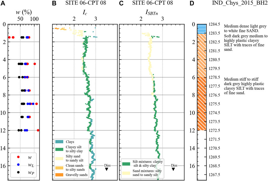
FIGURE 8. (A) Water content and plastic limits from borehole site Chys_2015 from database (SAFER/GEO-591; Gilder et al., 2019a; Gilder et al., 2020) (B) soil behavior type designation Ic (Been and Jefferies, 1993) from the CPTu profile site 06 CPT08 (C) soil behavior type designation ISBTn (Robertson and Wride, 1998), updated in Robertson (2009) site 06 CPT08 (D) Chys_2015 borehole log.
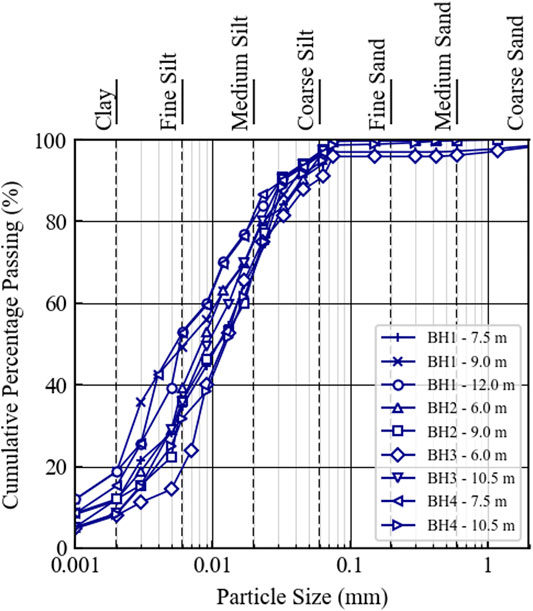
FIGURE 9. Particle size distribution data from boreholes at site 06-Chyasal (Chys_2015) (SAFER/GEO-591; Gilder et al., 2019a; Gilder et al., 2020) at 6.0–12.0 m depth.
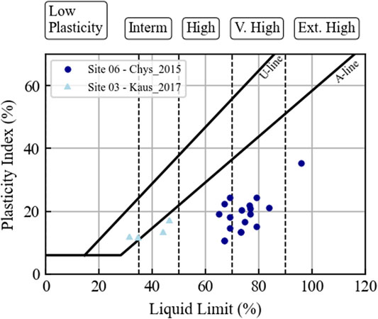
FIGURE 10. Casagrande soil classification chart site 06-Chyasal (Chys_2015) (SAFER/GEO-591; Gilder et al., 2019a; Gilder et al., 2020) at 1.5–12.0 m depth and site 03-Kausaltar up to 4.0 m depth.
The site visit to Kausaltar enabled evaluation of the Nkt factor, compared against both site-specific data (from field vane; Tiwari et al. (2018)) and database triaxial data from SAFER/GEO-591 (Gilder et al., 2019a; Gilder et al., 2020). Figure 11 shows the results. The factor Nkt is used for empirically predicting undrained shear strength, via relationship (qt − σvo)/cu. The selected value of 20 is at the high-end of typical estimates (upper value of 18 for fine-grained soils) but produces results only partially consistent with the database information of cu from similar sites at similar elevations. This empirical value overestimates the cu of the silts. Where cone resistance measurements are small, pore pressure data can be used to predict undrained strength using NΔu. However, this value is also on the upper bound of typical estimates (the value used is 10, typical range 7–10). Two explanations are possible; first, the triaxial dataset represents samples which have been disturbed during testing, or these tests do not represent similar soils (for the case of the database data) and second, the Nkt factor needs to be increased (resulting in the current estimates moving closer to the laboratory data). Given the reliability of the CPT method, the indication is that the former reason would be more likely and new laboratory data is needed to confirm this hypothesis.
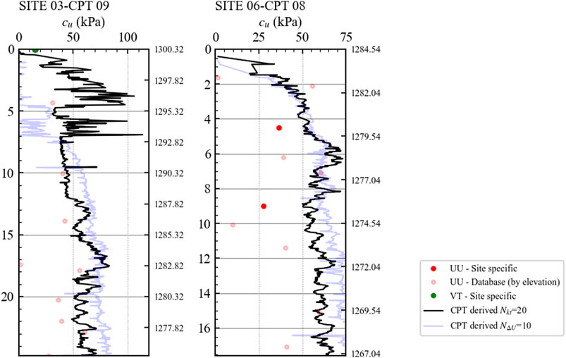
FIGURE 11. Derivation of undrained shear strength using an Nkt = 20 and NΔu = 10, comparison against both site-specific unconsolidated undrained triaxial (UU) and database UU tests in silts displayed by elevation.
At Satdobato (site 05) in Supplementary Figures SA6, SA7, the silt is interlayered with sands and organic soils. Again, in the silts/clays, the qt values are in the range of 30–1,650 kPa. Lastly, in Kirtipur Municipality (site 02), Supplementary Figures SA1–SA3 show that a more clay-like deposit is present from the surface, and this is the only location where thicker layers of organic material are indicated by the CPT. The three CPT’s that were undertaken at this location recorded very low qt values (average 420 kPa) and fs of between approximately 3 and 82 kPa in the clays. However, poor saturation of the pore pressure measurement system was encountered so no further information is available from these results.
The velocity profiles in Figure 6 indicate that the shear-wave velocity results do not vary significantly in the upper 20 m depth. In the silts and clays, the velocities are often at an average of around 150 m/s. At sites underlain by recent deposits, either flood plain or river terrace, the mixed materials show varying results on the same site (e.g., site 07). Variation at shallow depths can also be the result of the presence of possible made ground and is also affected by the analysis method (Stolte and Cox, 2020).
Liquefaction Evaluation
Due to the limited availability of detailed engineering profiles in the Kathmandu valley, estimation of liquefaction susceptibility has previously relied upon regional scale hypothesis (Moss et al., 2017) and SPT-derived results (Piya et al., 2004). Although the CPTu results indicate a dominance of “silty clay to clayey silt” and “clay-like” soil behavior types, the unusual distribution of Kathmandu recorded liquefaction sites (Figure 12B), particularly at Kausaltar and near to Hattiban where silt boiling was observed (Hashash et al., 2015), a preliminary assessment is provided. The methodology of Kayen et al. (2013) was used to assess liquefaction as it provides a way of determining the probability of liquefaction trigging based on the shear-wave results, which puts less emphasis on the fines content and is developed from case history information that includes data from higher intensity earthquakes, like in Nepal, from regions in Asia and some of this data includes velocity values amounting from marginal soils (those with higher fines contents and marginal plasticity). Employing this methodology requires some assumptions, for example, the soils in Kathmandu may have a unique soil-specific relationship between void ratio and relative density, which is not represented by the database (Kayen et al. (2013)) used to produce the liquefaction assessment procedure. However, the solution can be computed for critical layers at each site to assess the probable resistance.
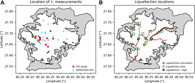
FIGURE 12. (A) Contribution of study in increasing the number of shear-wave measurements in the valley taken from previous sources described in SAFER/GEO-591 (Gilder et al., 2019a; Gilder et al., 2020). (B) Comparison of locations with areas of known ground deformation or liquefaction from previous field reconnaissance (Hashash et al., 2015) (green squares) and the areas of highest liquefaction from previous study. Liquefaction calculation locations correspond to later figures.
Using the procedure in Kayen et al. (2013), the seismic demand is estimated for a critical layer by calculating the nonlinear shear mass participation factor rd parameter, originally established in the simplified method produced by Seed and Idriss (1971), estimated using the equation provided by Cetin et al. (2004). A value for Vs,12 is calculated for each site and ranges between 130 and 207 m/s. The cyclic stress ratio CSR is then calculated:
where amax is the peak horizontal ground acceleration (set at 1.6 m/s2 for the case of the Gorkha earthquake) and g is the acceleration due to gravity. This equation is used at each increment of depth at each CPT location with corresponding shear-wave measurement. The CSR calculated for each depth increment of the profile is then used to assign a probability of liquefaction for each increment (Eq. 3) and the corresponding CRR (Eq. 4) from Kayen et al. (2013):
PL is the probability of liquefaction and CRR is the cyclic resistance ratio, where Mw is the moment magnitude, FC is the fines content, Vs1 = Vs(Pa/σ′v0)0.25, and the term Φ represents the cumulative normal distribution. Vs1 and CRR are plotted by depth in Figures 13A,B, respectively. At the lower elevations, this method of calculating CRR is used with caution, as in this case it is applied to materials with fines content of greater than 35%, and the calculation is currently applied with this maximum assumed due to the lack of accompanying grain size data for the majority. The understanding is that the values of fines content are likely much higher, and the existing database is currently inadequate for the soils at each location. Lastly, the CSR is adjusted from that in Eq. 2 to the duration of the chosen event (in this case the Gorkha earthquake) to CSR* (Kayen et al., 2013).
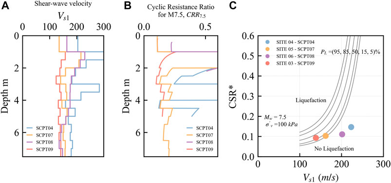
FIGURE 13. (A)Vs1 with depth (B) Cyclic resistance ratio in critical layers (C) Plot of the probabilistic liquefaction curves from Kayen et al. (2013) using Mw = 7.5, σ′v = 100 kPa and FC = 35%, compared against results from each site.
The critical layer at Kausaltar was selected as between 0.5 and 5.0 m depth (an average is taken across all data points in this range and this is the point presented in Figure 13C). This interval represents a range of Ic designations and so a range of material behaviors between clean sands to potentially silty clay (see Figure 5). Similarly, at Dhobighat (site 04), a critical layer is set between 0.5 and 4.0 m; at Satdobato (site 5) between 0.5 and 7.5 m; and lastly Chyasal (site 6) between 0.5 and 2.0 m. These results at Chyasal (site 06) are, however, problematic as the critical layer selected is within the top 2.0 m and this is where the calculation of VS1 is typically elevated. This result is using a capped Cvs value of 1.5 (Kayen et al., 2013) in the upper 1.0 m and all results in Figure 13C are with the upper 0.5 m excluded from the averaging to reduce this effect.
Examining the results in Figure 13C and by comparing them to the locations of liquefaction evidence in Figure 12B, those closest to liquefaction locations are in accordance with the calculated probability of liquefaction. However, although both beside rivers and in an area of the maps typically designated as having a “high” liquefaction potential in previous studies, site 04 and site 06 are both presenting results identifying that they are unlikely to liquefy. At site 04, there is a thicker upper deposit of “sandy” and mixed materials, but these deposits are linked with higher shear-wave velocity measurements, reducing the probability of liquefaction triggering. Alternatively, at site 05, the upper 7.5 m used to produce the average which may include some materials (clays, clayey silts) which are less likely to liquefy, the Vs profile is at a consistently low average (≈150 m/s), therefore increasing its liquefaction potential. The liquefaction hazard maps and locations of evidence of liquefaction in Figure 12B also coincide with the result at site 03, Kausaltar where ground movements were evidenced following the Gorkha earthquake (e.g., Moss et al., 2015), and the calculated value is sitting between the 15–50% probability of liquefaction contours.
Although these predictions appear to coincide with field evidence, the results for the sites near rivers (shown in Figure 12B) are not in accordance with current liquefaction maps for the region. Consideration of these liquefaction results is preliminary and further investigation work is needed to confirm the results. Given these observations, it is expected that an enhanced methodology is needed (e.g., Shuttle and Cunning, 2007); also see Shuttle and Cunning (2008) for further discussion. The screening plot provided in Shuttle and Jefferies (2016) or variant of in Robertson (2016) resulting from the Shuttle and Cunning (2008) discussion is provided in Figure 14. This indicates that the fine-grained soils plot for the majority in the region that could strain soften post initial liquefaction.
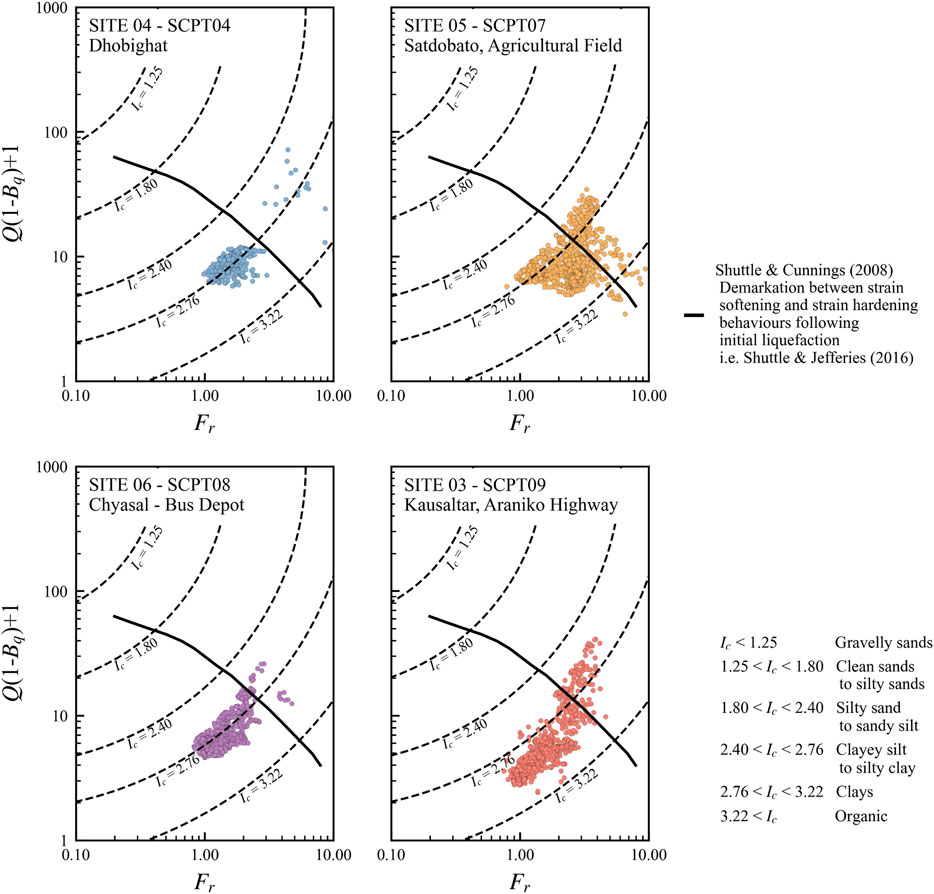
FIGURE 14. Site results plotted against friction ratio and dimensionless penetration resistance based on vertical stress and pore pressure, Q(1 − Bq) + 1. Points below the solid line can strain-soften.
Summary and Conclusion
This article has presented some new geotechnical field observations for the Kathmandu valley which have helped build a better understanding of the possible geotechnical impacts from earthquakes. Nearby rivers, the soils are saturated and are of a mixed composition which are typically difficult to classify and assess for liquefaction potential. These conditions, where there are excess pore water pressures (Δu) may mean that the soils have the potential to liquefy and, even within the well-established CPT and liquefaction frameworks are difficult to characterize. This makes the Kathmandu valley an important place for future testing of these existing CPT interpretation procedures and expansion of future work into understanding the specific parameters needed for the soils in Kathmandu. To share the gathered information and to enable further work in the future, the raw CPTu and shear-wave velocity results are provided in an online repository (Gilder et al., 2021).
The results of the interpretation of the soil profiles and the evidence of the soil condition allow for the following suggestions for further work to be made: 1) Further use of the cone penetration test with shear-wave velocity testing in the Kathmandu valley coupled with high-quality laboratory testing to supplement the conclusions of this study and support site-specific empirical parameters. Using a traditional sized CPT rig would likely see large increases in depths of penetration and help corroborate previous studies of deep unconsolidated sediments. 2) Liquefaction estimates likely need calibration in the region based on the dominance of fine-grained soils, and the CPTu testing so far has been within the predominantly clayey/silty soils in the southern portion of the valley where less interbedded sand layers are present. A laboratory regime which evaluates the critical state properties of the soils may assist engineers to better assess the liquefaction hazard in the area.
Data Availability Statement
Data are available at the University of Bristol data repository, data.bris, at https://doi.org/10.5523/bris.1271fsyng8y2z2cjyvlss1i8d2
Author Contributions
CG (first author)—site selection for field work; assistance with field work; processing of collected data; drafting of paper; RP—assistance with field work and proof-reading of paper drafts; FL—assistance with field work and proof-reading of paper drafts; PV (corresponding author)—project supervision; co-ordination of funding; review of the analysis and proof-reading of paper drafts.
Funding
The first author acknowledges the support of the Engineering and Physical Science Research Council (EPSRC) (EP/R51245X/1). The authors acknowledge the support of the EPSRC project “Seismic Safety and Resilience of Schools in Nepal” SAFER (EP/P028926/1) and Professor Anastasios Sextos for his support and leadership of the SAFER project. The authors also acknowledge the support of the University of Bristol Faculty of Engineering: Research Pump Priming funding.
Conflict of Interest
The authors declare that the research was conducted in the absence of any commercial or financial relationships that could be construed as a potential conflict of interest.
Acknowledgments
Many thanks are given to IN SITU Site Investigation for the significant in-kind contribution and particularly to Darren Ward and Sam Pyott for which the CPT work would not be possible. Additionally, the authors would like to thank NSET-Nepal, with particular thanks to Surya Shrestha and Narayan Marasini for their invaluable collaboration and support.
Supplementary Material
The Supplementary Material for this article can be found online at: https://www.frontiersin.org/articles/10.3389/fbuil.2021.646009/full#supplementary-material
LIST OF SYMBOLS
Ac cross-sectional area of cone
amax peak horizontal ground acceleration at surface
Bq pore pressure ratio, Bq = (u2 − u0)/(qt − σvo)
cu undrained shear strength
c′ apparent cohesion
CF clay fraction
CPT Cone Penetration Test
CPTu Cone Penetration Test (more specifically when using a piezocone which can record pore pressure)
CRR cyclic resistance ratio
CSR cyclic stress ratio
CSR* duration corrected Cyclic Stress Ratio
Cvs shear-wave velocity stress correction (=(Pa/σ′v0)0.25)
FC fines content
fs sleeve friction
Fr normalized friction ratio, Fr = fs/(qt − σv0) 100(%)
g acceleration due to gravity
Gmax small-strain shear modulus
Ic soil classification index (Been and Jefferies, 1993), Ic = [{3 − log[Q (1 − Bq) + 1]}2 + {1.5 + 1.3(log Fr)}2]0.5
ISBT non-normalized soil behavior type index (Robertson, 2010), ISBT = [(3.47 − log(qt/Pa))2 + (log Rf + 1.22)2]0.5
ISBTn normalized soil behavior type index (Robertson, 2009), ISBTn = [(3.47 − log(Qtn))2 + (log Fr +1.22)2]0.5
n stress normalization factor, in this study, defined using relationship n = 0.381(ISBT) + 0.05(σ′v0/Pa) − 0.15
Nkt empirical parameter required to calculate undrained shear strength (=(qt − σvo)/cu)
NΔu empirical parameter required to calculate undrained shear strength (=(u2 − u0)/cu)
Mw moment magnitude
Pa atmospheric pressure (= 0.1 in MPa)
PL probability of liquefaction triggering
qc cone tip resistance
qt corrected total cone tip resistance, qt = qc + u2(1 − α), where α cone area ratio (this study = 0.8)
qn net cone resistance, qn = qt − σv0
Q dimensionless CPT resistance based on vertical stress (or Qt1), Q = (qt − σv0)/σ ′v0
Q(1 − Bq) + 1 dimensionless CPT resistance based on vertical stress and pore pressure (Been and Jefferies, 1993), Q (1 − Bq) + 1 = (qt − u2)/σ′v0
Qtn dimensionless CPT resistance (Robertson, 2009), Qtn = [(qt − σv0)/Pa] (Pa/σ′v0)n
Rf non-normalized friction ratio, Rf= fs/qt 100(%)
rd nonlinear shear mass participation factor, originally Seed and Idriss (1971) updated Cetin et al. (2004).
SPT standard penetration test
SPT-N standard penetration test result (N-value)
u2 pore pressure (measured at shoulder of cone)
u0 equilibrium pore pressure
Δu excess pore pressure (=(u2 ‒ u0))
ϕ representing the cumulative normal distribution
Vs seismic shear-wave velocity
Vs1 normalized shear-wave velocity, Vs1 = Vs (Pa/σ′v0)0.25
Vs,12 average shear-wave velocity calculated in the top 12 m
VT Vane Test
w water content
wP plastic limit
wL liquid limit
σv0 in situ vertical total stress
σ ′v0 in situ vertical effective stress
ϕ′ effective friction angle
References
Andrus, R. D., Mohanan, N. P., Piratheepan, P., Ellis, B. S., and Holzer, T. L. (2007). “Predicting shear-wave velocity from cone penetration resistance,” in Proceedings of 4th International Conference on Earthquake Geotechnical Engineering, Thessaloniki, Greece, Paper No. 1454.
Asimaki, D., Mohammadi, K., Mason, H. B., Adams, R. K., Rajaure, S., and Khadka, D. (2017). Observations and simulations of basin effects in the Kathmandu valley during the 2015 Gorkha earthquake sequence. Earthquake Spectra 33 (S1), S35–S53. doi:10.1193/013117eqs022m
Aydan, Ö., and Ulusay, R. (2015). A quick report on the 2015 Gorkha (Nepal) earthquake and its geo-engineering aspects. Available from: https://citeseerx.ist.psu.edu/viewdoc/download?doi=10.1.1.733.9209&rep=rep1&type=pdf (Accessed February 12, 2021).
Been, K., and Jefferies, M. G. (1993). “Towards systematic CPT interpretation,” in Proceedings of the Wroth memorial symposium, predictive soil mechanics. Editors G. T. Houlsby, and A. N. Schofield (London, UK: Thomas Telford), 121–134.
Been, K., Quiñonez, A., and Sancio, R. B. (2010). “Interpretation of the CPT in engineering practice. Keynote Lecture,” in Proceedings of CPT’10, 2nd international symposium on cone penetration testing, Huntington Beach, CA, May, 2010, 27–45.
Boulanger, R. W., and Idriss, I. M. (2014). CPT and SPT based liquefaction triggering procedures. Report No.: UCD/CGM-14/01. Available at: https://faculty.engineering.ucdavis.edu/boulanger/wp-content/uploads/sites/71/2014/09/Boulanger_Idriss_CPT_and_SPT_Liq_triggering_CGM-14-01_20141.pdf?849d7a (Accessed February 02, 2021).
Cetin, K. O., Seed, R. B., Der Kiureghian, A., Tokimatsu, K., Harder, L. F., Kayen, R. E., et al. (2004). Standard penetration test-based probabilistic and deterministic assessment of seismic soil liquefaction potential. J. Geotech. Geoenviron. Eng. 130 (12), 1314–1340. doi:10.1061/(asce)1090-0241(2004)130:12(1314)
De Risi, R., De Luca, F., Gilder, C. E. L., Pokhrel, R. M., and Vardanega, P. J. (2020). The SAFER geodatabase for the Kathmandu valley: Bayesian kriging for data-scarce regions, Earthquake Spectra. doi:10.1177/8755293020970977
Fujii, R., and Sakai, H. (2002). Paleoclimatic changes during the last 2.5 myr recorded in the Kathmandu basin, Central Nepal himalayas. J. Asian Earth Sci. 20 (3), 255–266. doi:10.1016/s1367-9120(01)00048-7
Gilder, C. E. L., Pokhrel, R. M., De Luca, F., and Vardanega, P. J. (2021). Supporting data for “Insights from CPTu and seismic cone testing in the Kathmandu valley, Nepal”. Bristol, United Kingdom: University of Bristol. doi:10.5523/bris.1271fsyng8y2z2cjyvlss1i8d2
Gilder, C. E. L., Pokhrel, R. M., and Vardanega, P. J. (2019b). “A ground investigation to inform earthquake hazard assessment in the Kathmandu valley, Nepal,” in Proceedings of the XVII European conference on soil mechanics and geotechnical engineering (ECSMGE), September 2019: geotechnical engineering foundation of the future, (Reykjavík, Iceland: Icelandic Geotechnical Society). Available at: https://www.issmge.org/uploads/publications/51/75/0110-ecsmge-2019_Gilder.pdf (Accessed February 12, 2021).
Gilder, C. E. L., Pokhrel, R. M., and Vardanega, P. J. (2019a). The SAFER borehole database (SAFER/GEO-591_v1.1). Bristol, United Kingdom: University of Bristol. doi:10.5523/bris.3gjcvx51lnpuv269xsa1yrb0rw
Gilder, C. E., Pokhrel, R. M., Vardanega, P. J., De Luca, F., De Risi, R., Werner, M. J., et al. (2020). The SAFER geodatabase for the Kathmandu Valley: geotechnical and geological variability. Earthquake Spectra 36 (3), 1549–1569. doi:10.1177/8755293019899952
Giordano, N., De Luca, F., and Sextos, A. (2021). Analytical fragility curves for masonry school building portfolios in Nepal. Bull. Earthquake Eng. 19, 1121–1150. doi:10.1007/s10518-020-00989-8
Goda, K., Kiyota, T., Pokhrel, R. M., Chiaro, G., Katagiri, T., Sharma, K., et al. (2015). The 2015 Gorkha Nepal earthquake: insights from earthquake damage survey. Front. Built Environ. 1:8, 1–15. doi:10.3389/fbuil.2015.00008
Hashash, Y. M. A., Tiwari, B., Moss, R. E. S., Asimaki, D., Clahan, K. B., Kieffer, D. S., et al. (2015). Geotechnical field reconnaissance: Gorkha (Nepal) Earthquake of April 25 2015 and related Shaking sequence. Geotechnical Extreme Event Reconnaissance Association Report No. GEER-040.
Hegazy, Y. A., and Mayne, P. W. (2006). “A global statistical correlation between shear wave velocity and cone penetration data,” in Site and geomaterial characterization. GSP 149. Editors A. J. Puppala, D. Fratta, K. Alshibli, and S. Pamukcu (Reston, VA: American Society of Civil Engineers), 243–248. doi:10.1061/40861(193)31
J-RAPID (2016). Japan-Nepal urgent collaborative projects regarding the April 2015 Nepal earthquake within the J-rapid program: investigation of foundation liquefaction susceptibility in the Kathmandu valley (final report). Tokyo, Japan: Japan Science and Technology Agency.
Jefferies, M., and Been, K. (2006). Soil liquefaction—a critical state approach. 2nd Edn., (Abingdon, United Kingdom: Taylor and Francis).
Jefferies, M. G., and Davies, M. P. (1991). Soil classification by the cone penetration test: discussion. Can. Geotech. J. 28 (1), 173–176. doi:10.1139/t91-023
JICA (1990). Groundwater management project in Kathmandu valley. Tokyo, Japan: Japan International Co-operation Agency.
Katel, T. P., Upreti, B. N., and Pokharel, G. S. (1996). Engineering properties of fine-grained soils of Kathmandu Valley Nepal. J. Nepal Geol. Soc. 13, 121–138.
Kayen, R., Moss, R. E. S., Thompson, E. M., Seed, R. B., Cetin, K. O., Kiureghian, A. D., et al. (2013). Shear-wave velocity-based probabilistic and deterministic assessment of seismic soil liquefaction potential. J. Geotech. Geoenviron. Eng. 139 (3), 407–419. doi:10.1061/(asce)gt.1943-5606.0000743
Lunne, T., Robertson, P. K., and Powell, J. M. (1997). Cone penetration testing in geotechnical practice. London, United Kingdom: Blackie Academic and Professional, Boundary Row.
Madiai, C., and Simoni, G. (2004). “Shear wave velocity-penetration resistance correlation for Holocene and Pleistocene soils of an area in central Italy,” in Proceedings ISC-2 on geotechnical and geophysical site characterization. Editors V. da Fonseca, and Mayne (Rotterdam, Netherlands: Millpress), 1687–1694.
Mayne, P. W., and Kulhawy, F. H. (1995). “First-order estimate of yield stresses in clays by cone and piezocone,” in Proceedings cone penetration testing ‘95, Linköping, Sweden, October, 1995, Vol 2, 221–226.
Moss, R. E. S., Baise, L. G., Zhu, J., and Kadkha, D. (2017). Examining the discrepancy between forecast and observed liquefaction from the 2015 Gorkha, Nepal, earthquakes. Earthquake Spectra 33 (Sl), S73–S83. doi:10.1193/120316eqs220m
Moss, R. E. S., Thompson, E. M., Scott Kieffer, D., Tiwari, B., Hashash, Y. M. A., Acharya, I., et al. (2015). Geotechnical effects of the 2015 magnitude 7.8 Gorkha, Nepal, earthquake and aftershocks. Seismological Res. Lett. 86 (6), 1514–1523. doi:10.1785/0220150158
Ohsumi, T., Mukai, Y., and Fujitani, H. (2016). Investigation of damage in and around Kathmandu valley related to the 2015 Gorkha, Nepal earthquake and beyond. Geotech Geol. Eng. 34 (4), 1223–1245. doi:10.1007/s10706-016-0023-9
Olsen, R. S. (1997). “Cyclic liquefaction based on the cone penetrometer test,” in NCEER workshop on evaluation of liquefaction resistance of soils, Salt Lake City, UT, December, 1997, 225–276.
Piya, B. K. (2004). Generation of a geological database for the liquefaction hazard assessment in Kathmandu Valley. MSc thesis, Enschede (Netherlands): International Institute for Geo-Information Science and Earth Observation.
Piya, B., Van Western, C., and Woldai, T. (2004). Geological database for liquefaction hazard analysis in the Kathmandu valley, Nepal. J. Nepal Geol. Soc. 30, 141–152. doi:10.3126/jngs.v30i0.31704
Powell, J. J. M., and Butcher, A. P. (2004). “Small strain stiffness assessments from in situ tests—Revisited,” in Proceedings of the 2nd International Conference on Site Characterization, (Isc’2), Porto, Portugal, September, 2004, 1, 1717–1722.
Robertson, P. K., and Campanella, R. G. (1983a). Interpretation of cone penetration tests. Part I: sand. Can. Geotech. J. 20 (4), 718–733. doi:10.1139/t83-078
Robertson, P. K., and Campanella, R. G. (1983b). Interpretation of cone penetration tests. Part II: clay. Can. Geotech. J. 20 (4), 734–745. doi:10.1139/t83-079
Robertson, P. K., and Campanella, R. G. (1985). Liquefaction potential of sands using the CPT. J. Geotechnical Eng. 111 (3), 384–403. doi:10.1061/(asce)0733-9410(1985)111:3(384)
Robertson, P. K. (2016). Cone penetration test (CPT)-based soil behaviour type (SBT) classification system—an update. Can. Geotech. J. 53 (12), 1910–1927. doi:10.1139/cgj-2016-0044
Robertson, P. K. (2009). Interpretation of cone penetration tests—a unified approach. Can. Geotech. J. 46 (11), 1337–1355. doi:10.1139/t09-065
Robertson, P. K. (2010). “Soil behaviour type from the CPT: an update,” in Proceedings of CPT’10, 2nd international symposium on cone penetration testing. Huntington Beach, CA, May, 2010.
Robertson, P. K., and Wride, C. (1998). Evaluating cyclic liquefaction potential using the cone penetration test. Can. Geotech. J. 35 (3), 442–459. doi:10.1139/t98-017
Sakai, H., Fuji, R., Sugimoto, M., Setoguchi, R., and Raj Paudel, M. (2016). Two times lowering of lake water at around 48 and 38 ka, caused by possible earthquakes, recorded in the Paleo-Kathmandu lake, central Nepal Himalaya. Earth, Planets and Space 68 (31). doi:10.1186/s40623-016-0413-5
Sakai, H. (2001). Stratigraphic division and sedimentary facies of the Kathmandu basin group, central Nepal. J. Nepal Geol. Soc. 25 (Special Issue), 19–32.
Schneider, J. A., McGillivray, A. V., and Mayne, P. W. (2004). “Evaluation of SCPTU intra-correlations at sand sites in the lower Mississippi river valley, United States,” in Proceedings ISC-2 on geotechnical and geophysical site characterization. Editors V. da Fonseca, and Mayne (Rotterdam, Netherlands: Millpress), 1003–1010.
Schneider, J. A., Randolph, M. F., Mayne, P. W., and Ramsey, N. R. (2008). Analysis of factors influencing soil classification using normalized piezocone tip resistance and pore pressure parameters. J. Geotech. Geoenviron. Eng. 134 (11), 1569–1586. doi:10.1061/(asce)1090-0241(2008)134:11(1569)
Seed, H. B., and Idriss, I. M. (1971). Simplified procedure for evaluating soil liquefaction potential. J. Soil Mech. Foundations Division (ASCE) 97 (SM9), 1249–1273. doi:10.1061/jsfeaq.0001662
Shrestha, O. M., Koirala, A., Karmacharya, S. L., Pradhananga, U. B., Pradhan, R., and Karmacharya, R. (1998). Engineering and environmental geological map of the Kathmandu valley, scale 1:50,000. Lainchaur, Kathmandu: Department of Mines and Geology, His Majesty’s Government of Nepal.
Shuttle, D. A., and Cunning, J. (2007). Liquefaction potential of silts from CPTu. Can. Geotech. J. 44 (1), 1–19. doi:10.1139/t06-086
Shuttle, D. A., and Cunning, J. (2008). Reply to the discussion by Robertson on “liquefaction potential of silts from CPTu”. Can. Geotech. J. 45 (1), 142–145. doi:10.1139/t07-119
Shuttle, D., and Jefferies, M. (2016). Determining silt state from CPTu. Geotechnical Res. 3 (3), 90–118. doi:10.1680/jgere.16.00008
Stevens, V. L., Shrestha, S. N., and Maharjan, D. K. (2018). Probabilistic seismic hazard assessment of Nepal. Bull. Seismological Soc. America 108 (6), 3488–3510. doi:10.1785/0120180022
Stolte, A. C., and Cox, B. R. (2020). Towards consideration of epistemic uncertainty in shear-wave velocity measurements obtained via seismic cone penetration testing (SCPT). Can. Geotech. J. 57 (1), 48–60. doi:10.1139/cgj-2018-0689
Tiwari, B., Pradel, D., Ajmera, B., Yamashiro, B., and Khadka, D. (2018). Landslide movement at lokanthali during the 2015 earthquake in Gorkha, Nepal. J. Geotechnical Geoenvironmental Eng. 144 (3), 05018001. doi:10.1061/(asce)gt.1943-5606.0001842
United Nations. (2018). United Nations, department of economic and social affairs, population division. The World’s cities in 2018—data booklet (ST/ESA/SER.A/417). Available from: https://www.un.org/en/events/citiesday/assets/pdf/the_worlds_cities_in_2018_data_booklet.pdf (Accessed February 12, 2021).
USGS (2016). One year after the M7.8 Nepal earthquake—Scientists return to himalayan nation to learn lessons. Reston, VA: United States Geological Survey (USGS)Available at: https://www.usgs.gov/news/one-year-after-m78-nepal-earthquake (Accessed December 24, 2020).
Wair, B. R., DeJong, J. T., and Shantz, T. (2012). Guidelines for estimation of shear wave velocity profiles. PEER report 2012/08, pacific earthquake engineering research centre. Berkeley, CA: University of CaliforniaAvailable at: https://peer.berkeley.edu/sites/default/files/webpeer-2012-08-bernard_r._wair_jason_t._dejong_and_thomas_shantz.pdf (Accessed February 12, 2021).
Wilkinson, S., DeJong, M., Novelli, V., Burton, P., Tallet-Williams, S., Whitworth, M., et al. (2019). The MW 7.8 Gorkha, Nepal earthquake of 25 April 2015, A field report by EEFIT. London, United Kingdom: The Institution of Structural EngineersAvailable from: https://www.istructe.org/IStructE/media/Public/Resources/report-eefit-gorkha-nepal-20190812.pdf (Accessed February 12, 2021).
Yamashiro, B. (2017). Evaluation of cyclic mobility on fine grained soil due to earthquake induced ground motion, MSc thesis. Fullerton (CA): California State University.
Youd, T. L., and Idriss, I. M. (2001). Liquefaction resistance of soils: summary report from the 1996 NCEER and 1998 NCEER/NSF workshops on evaluation of liquefaction resistance of soils. J. Geotech. Geoenviron. Eng. 127 (4), 297–313. doi:10.1061/(asce)1090-0241(2001)127:4(297)
Keywords: CPTu, shear-wave velocity, Kathmandu valley, ground investigation, geotechnical testing
Citation: Gilder CEL, Pokhrel RM, De Luca F and Vardanega PJ (2021) Insights from CPTu and Seismic Cone Penetration Testing in the Kathmandu Valley, Nepal. Front. Built Environ. 7:646009. doi: 10.3389/fbuil.2021.646009
Received: 24 December 2020; Accepted: 15 February 2021;
Published: 07 May 2021.
Edited by:
Ioannis Anastasopoulos, ETH Zürich, SwitzerlandReviewed by:
Christos Vrettos, University of Kaiserslautern, GermanyPaolo Castaldo, Politecnico di Torino, Italy
Copyright © 2021 Gilder, Pokhrel, De Luca and Vardanega. This is an open-access article distributed under the terms of the Creative Commons Attribution License (CC BY). The use, distribution or reproduction in other forums is permitted, provided the original author(s) and the copyright owner(s) are credited and that the original publication in this journal is cited, in accordance with accepted academic practice. No use, distribution or reproduction is permitted which does not comply with these terms.
*Correspondence: Paul J. Vardanega, p.j.vardanega@bristol.ac.uk