To understand the creation of energy through sound vibration, today in this article we have come up with the small yet informative circuit called clap on-off switch. Basically, the load of this circuit gets turned on or off by the human hand clap. Hence, the circuit is very suitable for beginner of electronics students who are also willing to research different sources of energy. To make this circuit IC 4017 is the major electronic component that gets utilized in making the circuit.
CD4017 IC is considered one of the most reasonable counters IC. It’s primarily the IC that provides ten decoded outputs and enables to count from zero to ten. CD4017 is a CMOS decade divider or counter, having 10 output pins. That’s why this IC gets utilized in every industry including medical, electronics, automotive industry, etc. The best part is that it takes very little space in the circuits or in the devices, which makes it more promising to use. also, the IC is available at very affordable prices in the electronic market.
Hardware Components
The following components are required to make Clap Switch Circuit
| S.no | Component | Value | Qty |
|---|---|---|---|
| 1. | Breadboard | – | 1 |
| 2. | Resistor | 22k, 1k, 470 ohm | 1, 1, 1 |
| 3. | LED | – | 1 |
| 4. | Battery | 9v | 1 |
| 5. | Counter IC | CD4017 | 1 |
| 6. | Relays | 6v | 1 |
| 7. | Transistor | BC547 | 2 |
| 8. | Mic | – | 1 |
| 9. | Bulb | – | 1 |
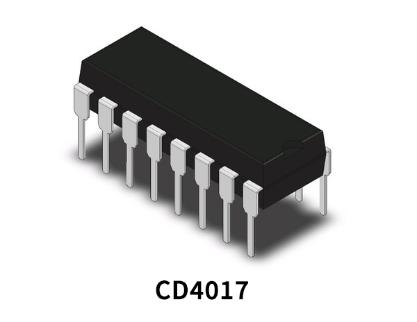
CD4017 Pinout

For a detailed description of pinout, dimension features, and specifications download the datasheet of CD4017
BC547 Pinout

For a detailed description of pinout, dimension features, and specifications download the datasheet of BC547
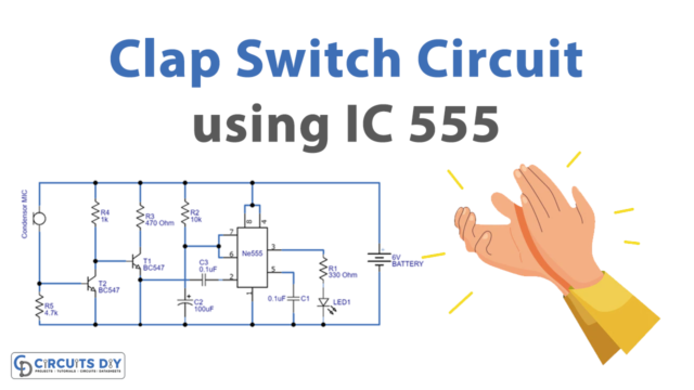
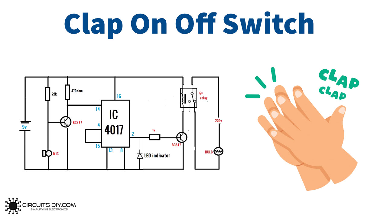
Clap Switch Circuit
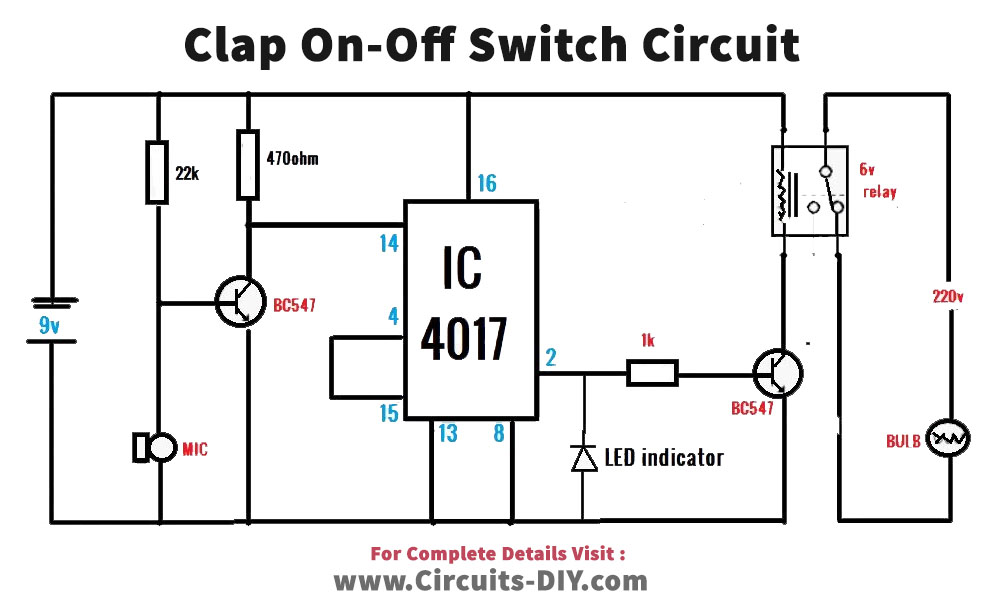
Working Explanation
Connect the clap on-off switch according to the above-given diagram Now, when you connect the 9V battery to that and start to clap, the sound vibration goes to the base of the transistor through the mic. Since this transistor is connected with pin 14 of the IC, which is the clock pin, therefore it gets triggered. The output pin two is wired with the base of the other output transistor, which is employed to drive the relay, Finally, the relay is there to turn on or off the attached load.
Application and Uses
- It can be used to research energy using sounds and vibration.
- To drive some AC loads.
- Also, if we try this circuit on a larger scale with some modification, it may be used in automation circuits.