
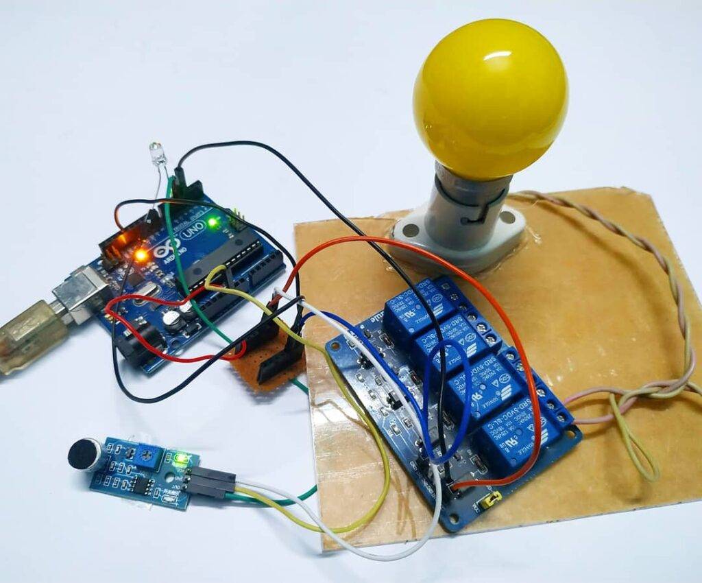
Hey geeks, welcome back to Techatronic. In this article, we are going to learn how you can make your own Clap Switch Using Arduino and KY-038 Sensor. I am sure that you all are aware of the working of the basic switches and their use. There are many types of switches available in the market, some of them have two or more terminals. Basically, a two-pin switch is most common among all. They are used in electrical networks to complete or break the circuits. We use an Arduino UNO microcontroller board to control the circuit and a KY-038 sound sensor for detecting the clap sound which we have to produce. You can also check out more such cool projects based on Arduino and also try our E-book that comes along with Arduino starter kit to make your own working projects. In this project, we will make a digital switch that works automatically. Please make the circuit according to the given diagram and then upload the given Arduino code.
How Does it Work?
We use a KY-038 sound sensor that generates a high output whenever it detects a sound signal. If you are not familiar with the working of the sound sensor with Arduino then please check it out first. We have to clap to generate a loud sound so the sensor will detect it. When you clap near the sound sensor the LED will go on when you clap again the LED goes off. There are two given circuits and you can make any one of your choices. One circuit is designed to turn on and off an AC bulb and the other is for an LED. Please work carefully with the AC load.

Components Required
- Arduino UNO
- USB cable for uploading the code
- KY-038 sound sensor
- Red LED
- 220-ohm resistor
- Single-channel relay module
- AC bulb
- Jumper wires
Circuit Diagram for Clap Switch
- Clap Switch for AC bulb

Connect the 5-volts and GND pin of the Arduino with the VCC and GND pin of the sound sensor. Attach the A0 pin of the sound sensor with the analog-0 pin of the Arduino and the D0 pin of the sound sensor with the digital-2 pin of the Arduino. Join the positive wire of the LED with the digital-9 pin of the Arduino and the negative wire of the LED with the GND pin of the Arduino via a 220-ohm resistor as shown. Connect the 5-volts and GND pin of the Arduino with the VCC and GND pin of the relay module and data pin of the relay module with the digital-10 pin of the Arduino. On the opposite side of the relay module connect one wire of domestic AC supply and on the other pin attach a wire from the bulb. Join the other wire of AC supply to the bulb and your clap switch is ready.

- Clap switch for LED
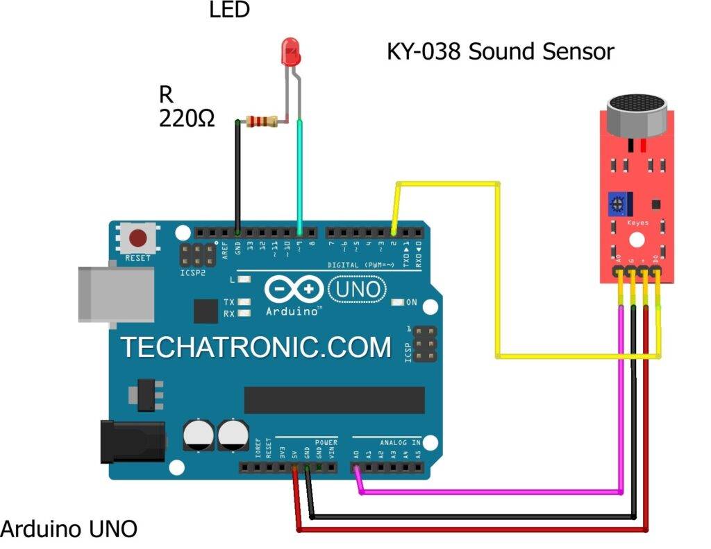
Make the same connections for the sound sensor and LED as shown in the above diagram. After completing the circuit make sure to upload the given code.
Code of the Project
NOTE: Please upload the given code according to the circuit you made.

- Code for AC bulb clap switch
 // TECHATRONIC.COM
 int SoundSensor=2; // LM393 Sound Sensor Digital Pin D0 connected to pin 2
 int LED=9;     // LED connected to pin 9
 int RELAY=10;   // RELAY connected to pin 10
 boolean LEDStatus=false;
 void setup()
 {
  pinMode(SoundSensor,INPUT);
  pinMode(LED,OUTPUT);
  pinMode(RELAY,OUTPUT);
  Serial.begin(9600); //initialize serial
  digitalWrite(RELAY,HIGH); // RELAY High means OFF
 }
 void loop()
 {
  int SensorData=digitalRead(SoundSensor);
  Serial.println(SensorData);//print the value
   if(SensorData==1)
   {
   if(LEDStatus==false)
   {
     LEDStatus=true;
     digitalWrite(LED,HIGH);  // LED ON
     digitalWrite(RELAY,LOW); // RELAY OFF
   }
   else if(LEDStatus==true)
   {
     LEDStatus=false;
     digitalWrite(LED,LOW);  // LED ON
     digitalWrite(RELAY,HIGH); // RELAY OFF
   }
   }
   }
- Code for LED clap switch
 // TECHATRONIC.COM
 int SoundSensor=2;  // LM393 Sound Sensor Digital Pin D0 connected to pin 2
 int LED=9;      // LED connected to pin 9
 boolean LEDStatus=false;
 void setup()
 {
  pinMode(SoundSensor,INPUT);
  pinMode(LED,OUTPUT);
  Serial.begin(9600); //initialize serial
 }
 void loop()
 {
  int SensorData=digitalRead(SoundSensor);
  Serial.println(SensorData);//print the value
   if(SensorData==1)
   {
   if(LEDStatus==false)
   {
     LEDStatus=true;
     digitalWrite(LED,HIGH); // LED ON
   }
   else if(LEDStatus==true)
   {
     LEDStatus=false;
     digitalWrite(LED,LOW); // LED OFF
   }
   }
   }
Hope you understand the project well and if you are facing any errors do inform us in the comments section below. You can also check out more Arduino Tutorials.
HAPPY LEARNING!
Sponsor:

Bored of soldering circuits on PerfBoard. PCBWay provides awesome PCB manufacturing service at a reasonable price. Gerber viewer along with other inspection tools available before submitting Gerber files finally. They also provide PCB Assembly service for SMD components PCB which may seem hard to solder. Multiple continuity and other tests are done on your order before departing them from warehouse. So order your first PCB at $5 of 1-2 layers in different colors on PCBWay.


I need a drone project control with phone